
 Introduction
Oblique Illumination is a cheap and easy method to enhance contrast in bright field microscopy by modulation of the condenser aperture plane. Current literature still claims there is no such theory to explain how oblique illumination will work.
Theory of oblique illumination
I'm a physicist with a long history of designing both, optical systems and data reduction techniques in digital image processing since the late 1980ies. The statement of non-existing theories about oblique illumination always makes me smile. Ernst Abbe (1881) was not the first, who used the term "oblique illumination" in his publication about the fundamental theory of the optical resolution of the microscope. Ernst Abbe's thoughts and theory have been revisited and reviewed multiple times and extended by many well-known physicists, like Rayleigh, Berek or Born just to mention a few important authors of follow-up publications at his time. People, who confirmed the effects of the optical nature light waves. Ernst Abbe's idea was carried over centuries and is one puzzle piece of the electro-magnetic theory in physics. In the 1940ies Max Born presented a comprehensive summary of current knowledge in his scholarly book about the electro-magnetic theory of light. Born deducted the optical resolution of the microscope using the mathematical idea of Fourier optics. Today, Fourier optics has many applications in microscopy, astronomy and other disciplines using optical systems.
The electro-magnetic theory not only explains optical resolution of the microscope. Results can be verified using a mathematical model. It is a model of the optical system using basics of light wave propagation. This theory allows to compare theoretical computations with real observations. Looking closer, theory introduces the interference of light waves propagation within the optical system. The electro-magnetic theory explains the complete optical imaging system.
Modern computers are a tool to compute and simulate the theoretical physical model of light wave propagation. Physics uses a simple trick to create the fundamental mathematical idea. Scholarly mathematics uses "real numbers". The set of real numbers are familiar to us: Those number with an integer value, a period and any number of digits of a fractional value. The set of real numbers will be extended by a single number "i", which solves the equation "x2+1=0". The resulting number "i" is the solution of this equation and can be thought of the square root of minus one (-1). Of course, certain scholarly mathematics treat this number as a forbidden solution in the set of real numbers. Within the set of real numbers the equation cannot be solved. This idea of "i" makes a huge difference: We can use "i" in order to model a light wave propagation. Light becomes a vector composed of a real and an imaginary scalar. That's why this special number was called "i" to refer to its imaginary nature. This mathematical construction created computed electromagnetic waves. Light can be computed. The electro-magnetic theory extends and replaces geometric optics. It explains the physical nature of wave propagation and interference. I don't want to go into mathematical details of this great theory. Mathematics is as complex, as the composite of a real number and an imaginary number is called the (mathematical) set of complex numbers. You need a few years playing around with numbers, computations and simulations to understand its nature. You got it.
Computer simulation of oblique illumination
The exact theory of using complex numbers to model and explain wave propagation is non-trivial. One has to consider a physical model of image formation of the microscope and also look closer at the details in the optical system. Using a bright field microscope we typically observe thick objects. Just a thin fraction of the object will provide a sharp image. Hence, we need to define a few assumptions about the object viewed:
- The transparent object viewed shall be considerably thin
- The complete optical system using Koehler illumination, from light source, condensor, object viewed, objective wo the final image in the human eye or any camera, needs to be simplified to save computation time
A simplification can be assumed, if we consider small objects like cell organelles. A high resolution water immersion microscope objective, for example, provides very sharp images and a high lateral resolution. The axial resolution of the optics, however, is worse, than the lateral resolution. For such optics, we yield about 1 µm of axial resolution, while the lateral resolution is in the order of 200-300 nm. Hence the thickness of a small sphere of 1 µm is an ideal candidate for our simulation. It will be resolved by the microscope as (circular image of) a sphere, while the lateral resolution will be within the sharp area of optical depth. Of course, also large objects will yield good results with oblique illumination. Of course, physicists are pragmatic people. If necessary, thick objects can be considered as numerically beaten as flat as possible, like veal escalopes. However, the use case of a microscope is different, as there is only a thin layer to consider in the image formation process. And this thin layer cannot be explained by geometrical optics.
The second assumption of our computer simulation tries to reduce the complete Koehler illumination to just a fraction of the whole microscope. We use similarity of condenser aperture plane and its image. The image of the condenser aperture plane will be imaged into the pupil plane of the microscope objective. This is, because condenser and objective form a composite optical system, this will grant the aperture plane of the condenser is visible within the objective aperture plane. Check it out: pull the eyepiece and have a look thorugh your microscope, how the condenser iris diaphragm image is visible in the back of your microscope objective. Similarity is granted. A few details are not really fullfilled, when moving condenser pupil into the objective. For the sake of simplicity, I'll leave mathematical considerations and corrections out here. We skipping additional computations from the illumination and condenser using these corrections. Now it becomes simpler and sufficient to compute numbers just between the target and its image in the microscope . Finally, we need to conserve the relations between the pixel dimension, object dimension, wavelength and diameter of the sphere viewed. These are important geometric relationships to be preserved within the different planes of the object plane, objective aperture plane and image plane. Otherwise, interference computations are not the same.
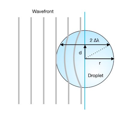
In the following we study a small transparent sphere with diameter 1 µm. We create a synthetic image using a theoretical computer model. The wavelength of the llight passing our sphere shall be 550 nm, which is visible light at maximum sensitivity of the human eyes perception. We also assume our sphere is located in surrounding water (diffractive index: 1.33). The sphere shall have a diffractive index similar to glycerol (diffractive index: 1.47). The sphere has a diffractive index, that is different from the surrounding medium (water). Small cell organelles have properties similar to these numbers. The difference of the diffractive index can also be changed to match the difference of the diffractive index of objects, like diatoms embedded in special resin. The objective shall be a high resolution microscope objective with numerical aperture of NA=1.2, like a water immersion or oil immersion objective.
Differences of the diffractive index of both, the sphere and surrounding medium causes light waves to be deferred within the object viewed. Depending on where the light will pass the sphere, the propagation of the light wave will suffer from a phase difference. Behind the sphere a discontinuous "jump" of the wave will occur, which causes interference of the light waves passing the object compared to the wave portion that passes the medium.
If there would be no sphere located in the medium, we would observe a homogeneous, white image. Now consider moving the sphere under microscope and see, what changes. If the sphere would have the same diffractive index, as the medium, there will be no change to light. We wouldn't simply find any sphere in the image from both cases.
The sphere is transparent, uncolored with no or just minor absorption. The wave front will be deferred from difference of the diffractive index compared to its original shape before passing the sphere. This deformation yields differences in interference fringes now. In addition the microscope objective will introduce diffraction at the borders of its entrance/exit pupil. From a physical point of view diffraction is the same as a special case of interference at borders, namely a bandpass or edge filter. Hence, I don't have to distinguish between both terms, interference and diffraction in the following writing.
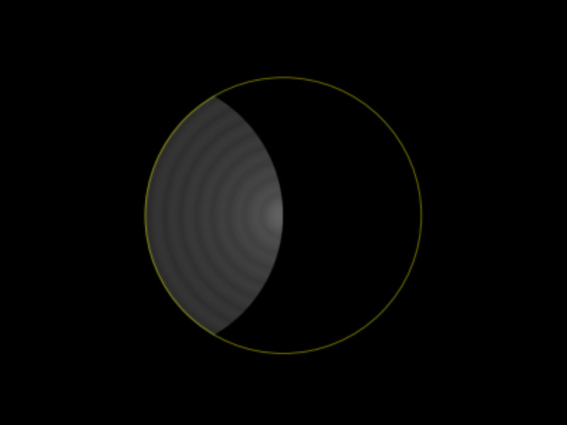
Interference of the light wave occurs between isoplanatic planes from the object through aperture of optics to the image plane. Interference will now create a distorted white image, because the transparent sphere lies in the object plane and causes deformation of the wave front. But, the sphere will just create a vague image of its existence. We observe a diffraction pattern, with a dark diffraction ring denoting the diameter of the sphere. This looks very much different from watching a sphere of glass in the macroscopic world! In bright field microscopy we just see a faint thing with low contrast against white background.

Certainly, it requires some training to become familiar watching through a microscope. Unmodified bright field illumination, however, is certainly the worst technique to watch transparent objects. That's why coloring techniques are so popular in microscopy. The faint image obtained from an uncolored sphere shown above is the mathematical proof.
Bright field microscopes use a condenser to condense illumination. Typical the condenser hosts a diaphram or multiple different diaphragms to support techniques, like bright field illumination, phase contrast or dark field illumination. Using such movable condenser diaphragms one is able to create oblique illumination by shifting bright field diaphragma a bit to the side. Alternatively, put a black sheet of paper into the condenser close to where its diaphragm is located. Pull the eyepiece and watch the back of your objective again. It will look similar to the following image. In my theoretical model I can create perfect oblique illumination that covers exactly half of the condenser aperture plane, like this.
Look, our sphere looks pretty much different! How does it work?
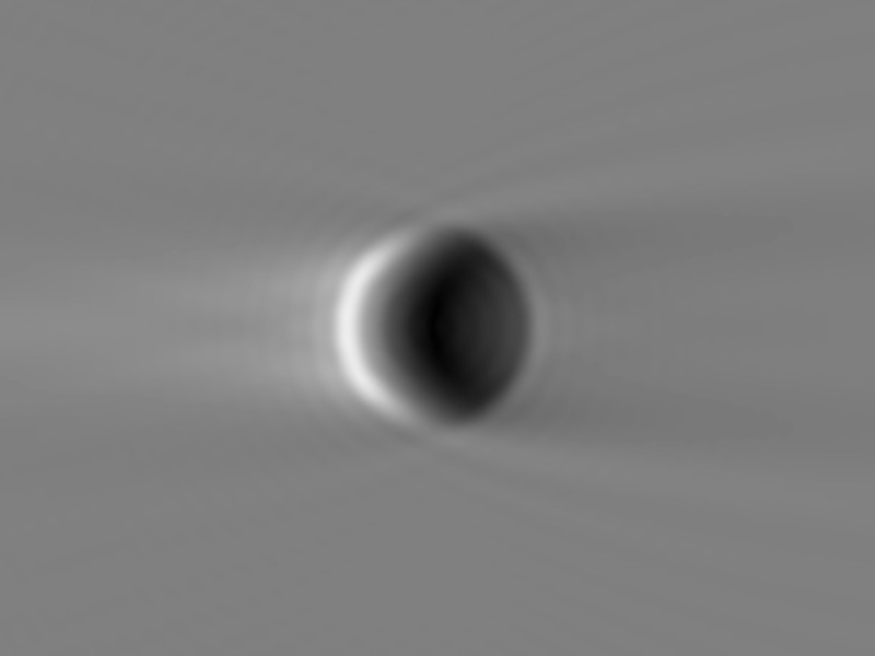
Oblique illumination, like shown above, will cause many parts of the light wave passing the target and objective to be dropped. A large portion of the wavefront has been discarded. Light waves with certain prefixes are now missing in the right part of both aperture planes of the condenser and microscope objective.
Consequently, certain portions of the light wave are also missing in the image plane. As if we would have shifted light waves from right to left. We've got a dark side of the condenser and its image in the aperture pupil plane. This does not result in shadowing, like it is the case in macroscopic worlds. The effects of light are caused by interference of light waves! Manipulation of image intensities are done at a scale of the wavelength of light, causing changes in constructive or destructive interference of light waves passing the optical system. This is what Ernst Abbe concluded in his summary:
„The very first step of every understanding of the Microscope is to abandon the gratuitous assumption of our ancestors, that microscopical vision is an imitation of macroscopical, and to become familiar with the idea that it is a thing sui generis, in regard to which nothing can be legitimately inferred from the optical phenomena connected with bodies of large size." – Ernst Abbe, 1881
Ernst Abbe und colleagues knew the phenomenon is based on wave propagation and interference. The computer model has computed an interference analysis of the optical imaging system, not an geometrical angle illumination of a macroscopic object. Fourier optics can explain both, interference fringes and also the geometrical relationship between the target and image. Likewise, the image of the target is rotated by 180 degrees from the mathematical computation as well. Two Fourier transformations need to be processed: From target plane to objective aperture plane, and then from here to the image plane. This will introduce a flipped image as a result of a negative sign on both axes. The optical image is the result of complex interference and wave propagation within the three planes considered. The contrasted image of the sphere is a result of constructive or destructive interference pattern in the image plane from oblique illumination. It is valid, oblique illumination is a technique of interference contrast.
Rocket Science or Wave-Particle Dualism?
When one gets familiar with adjustment of oblique illumination, the observer will notice slight deviation between the predicted image from theory and any practical image taken with a digital camera. Interference fringes may look different. Having hand at the focus knob one will intuitively try different focal planes to let the sphere look nice. The human eye and brain has a different perception, of how the sphere should look fantastic. Of course, the theoretical model can be extended to also simulate the observers hand at the focus knob.
The theoretical model is able predict observed effects well. Theoretical and practical focal planes will differ at the observers own discretion. We have a different idea of how the sphere shall look like. One will observe the bright side or shadow may flip from one side to the other while searching for the right focal plane while focussing. We found important hints to have observed interference from light wave propagation, not geometrical angle illumination.
Oblique illumination is complex and also complex to understand. Oblique illumination undergoes subjective evaluation by the observer. All theory is grey, my friend. Humans tend to pick any personal ideal of nature. Even a physicist cannot be free from subjective evaluation. We try to let the sphere look aesthetic, which is any different dimension of reality. There will be certainly any demand for a revised theory of oblique illumination.
Oblique illumination is not rocket science. In fact it is more complex and harder to understand. Only a few people ever understood the basic concept from oblique illumination to also describe microscopic resolution. Poor child. We know particles of light may pass different wholes at the same time. We cannot even track the particle, instead find interference fringes. If we could track the particle, where in our optical system it will pass the condensor, like finding its geometric path walked, the observed interference fringes would break down immediately. This is a first emergency exit in the proper understanding of oblique illumination.
In this sense, I like to wish you a nice time playing around with oblique illumination at your microscope!
Literature
- Abbe E. On the Estimation of Aperture in the Microscope. J R Microsc Soc. 1881; 1: 388-423.
- Bauer T. Die perfekte schiefe Beleuchtung. Mikroskopie 4/2020. Dustri Verlag.
- Berek M. Über Kohärenz und Konsonanz des Lichtes. Z Phys. 1927; 40: 420-450.
- Born M. Optik. Ein Lehrbuch der elektro-magnetischen Lichttheorie, Berlin: Springer; 1981; Nachdruck der 3. Auflage, S. 182ff.
- Goodman JW. Introduction to Fourier Optics. 3rd Edition. Greenwood Village: Roberts & Company Publishers; 2004.